When you want to draw a big 3D scene with lots of contents, you want to minimize the number of draw-calls. One of the very first technique to implement is called Frustum culling, which consists of removing things that the camera cannot see.
This is the first part of a series of articles on 3D scene optimizations. More to come!
Perspective projection
But let's just remind the maths behind perspective projections before going further.
We want to transform the view frustum (simply called frustum in the rest of the article) into NDC (normalized device coordinates). NDC are basically your graphic API convention to say: "Hey bro, I will render only vertices that are within these positions. I don't have to know about your internal projections or such."
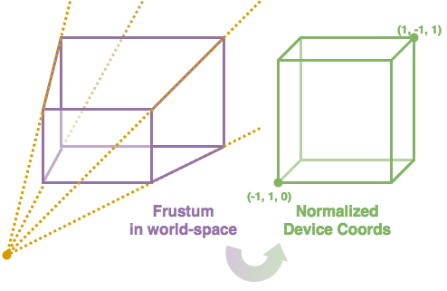 Our goal is to take any point inside the frustum to its NDC version.
Your camera is certainly a parametrable object with custom position and
rotation. But, we'll just let that aside, ok? This would be
another transformation matrix (called view). So let just say
that your camera is standing at the origin and looking towards +Z axis,
with +Y being up. In practice, just multiply your projected-to-be point
by the view matrix beforehand.
- x: -1 (left), 1 (right)
- y: -1 (top), 1 (bottom)
- z: 0 (near), 1 (far)
Let's just don't care about normalizations defined by NDC yet, and just go for simple perspective maths.
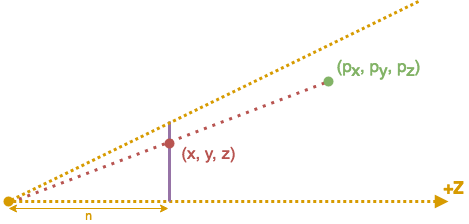 Projecting P point onto the near plane. Camera is at the origin.
We want to find y of the projected point. Thales' theorem gives us: y/py = n/pz. So you have your y value and you can do the very same for the x one. And, as you can notice, the projection makes it so that z = n. A simple matrix representation of this transformation is:
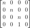 Homogeneous coordinates make that (px, py, pz, 1) is mapped to (npx, npy, npz, pz).
Once normalized, dividing all by the w coordinate, we get what we wanted.
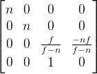
This is already somewhat useful, but your graphic API cannot use depth information, as it is always n. To prevent that, you know that you want 0 when pz = n (on the near plane), and 1 when pz = f (on the far plane).
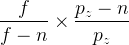 Injecting n and f into pz does give us 0 and 1.
Which gives the following matrix:
 Once you get used to it, writing those matrices matching the equation we initially wanted is pretty simple.
Consider that f / (f - n) ⟶ 1 and replace that in your matrix.
So, our z is now all right for the NDC, we still have to convert x and y projected values into the (-1, 1) range. For that, we need to define the FOV (field of view) and aspect ratio of your camera. Basically, the FOV is the view angle of your camera, there are two of those, the vertical one FOVy and the horizontal one FOVx. You can deduce one knowing the other thanks to the aspect ratio (you know, like 16:9).

From that, with simple trigonometry, we can say that:
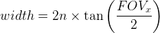 Where width is the one of the near plane section.
As we want to map x = -width / 2 to -1, and the same principle goes for y, we get:
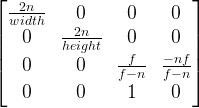 Final perspective projection matrix.
And that's it. In practice, there is no need for something more complex. Your near plane width and height are given by the previous formula with the corresponding FOV or by using the aspect ratio once knowing one of the two lengths.
Frustum culling
Frustum definition
For efficient computation, we will define our view frustum as a group of six planes.
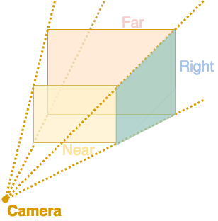 Here, only near, far and right planes are indicated.
I let you work out what left, top and bottom ones are.
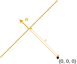
Even if they are represented as finite with rectangles, the planes are in fact infinite. Each plane is defined by its normal n and its distance d from the origin. You can visualize that the vector dn defines a point that is on the plane.
But if you just have a precomputed projection matrix, you might wonder how to get the planes. Well, we'll just try to extract three points of the plane.
// Getting homogeneous local coordinates
auto projectionInverse = inverse(projection);
auto topLeftLocal = projectionInverse * vec4(-1, -1, 0, 1);
auto bottomLeftLocal = projectionInverse * vec4(-1, 1, 0, 1);

/**
 * The above vec4(x, y, z, w) are projected coordinates:
 * x -> -1 (left),  1 (right)
 * y -> -1 (top),   1 (bottom)
 * z ->  0 (near)   1 (far)
 * w ->  1 (to work with homoneneous coordinates)
 *
 * Some subtilities can occur depending on technology used:
 * - Above are Vulkan conventions;
 * - OpenGL has z in range (-1, 1) and y inverted;
 * - Direct3D has y inverted.
 **/

// Normalizing coordinates and getting world-space ones
auto viewInverse = inverse(view);
auto topLeft = vec3(viewInverse * (topLeftLocal / topLeftLocal.w));
auto bottomLeft = vec3(viewInverse * (bottomLeftLocal / bottomLeftLocal.w));
We extract the positions of two points of the left plane.
After that, getting the normal of the left plane is pretty straight-forward.
We just have to be careful of the sign
of our normal. Here, leftNormal is pointing outside
the frustum volume. For the other ones (not detailed),
you should be consistent.
auto leftNormal = cross(topLeft - cameraPosition, bottomLeft - cameraPosition);
leftNormal = normalize(leftNormal);
The camera position is on each plane (except near and far),
so we have our three points.
The distance d can be computed as long as you have any point
of the plane. We'll use cameraPosition here.
auto leftDistance = dot(cameraPosition, leftNormal);
Getting the distance of the plane from the origin.
In fact, projecting any point of the plane onto the normal will do the trick.
length(cameraPosition) + clippingDistance,
where clippingDistance is what you used
to construct your perspective matrix (near or far clipping distance).
Having our six planes, checking that a point p is inside the frustum can be reduced to checking which side is a point according to each plane. Let's do it.
Plane side detection
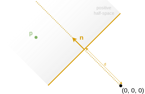
Having a plane defined by (n, d), one wants to know within which half-space is a certain point p.
To do so, one can simply project the object position onto the normal, extracting its norm as h.
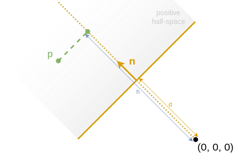 h = dot(n, p)
As n specifies one half-space (-n specifing the other one), we can say that:
- p is within the positive half-space iff h > d.
That means that we know where is p according to the plane.
But, in pratice, our game entities are not just points, they have a certain volume. The following image should convince you it's not a hard problem if you know the bounding volume radius r.
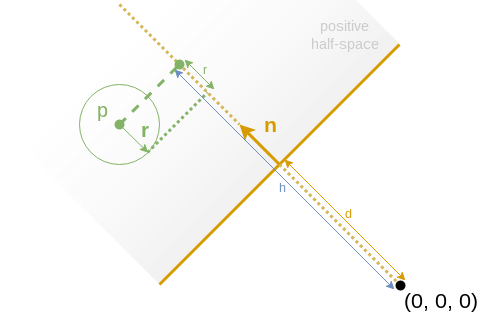
- h - r > d: the volume is completely within the positive half-space;
- h + r < d: the volume is completely within the negative half-space;
- else: the volume is crossing the plane.
Checking the six planes of the frustum, you can now discard any entity that's outside any of the planes.
Accelarated structures optimization
In pratice, your game entities are likely to be stored in acceleration structures. I will discuss how to implement them in later articles, but let just take a look at a classic BVH (bounding volume hierarchies).
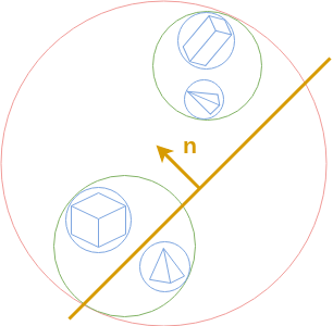 Red bounding sphere is the root one. Green are the level 1 bounding spheres. Blue are the level 2 ones.
If the bounding sphere is completely inside or outside your frustum, you can either accept or discard all leaf entities without more checking.
On the other hand, if it is crossing any plane, we will check against children nodes bounding spheres. But, we can be clever by forwarding information of the parent node to the children.
/**
 * planesToCheckFlags:
 *  Only specified planes are checked.
 *  The other ones are considered already tested to true.
 *     0x02: left plane
 *     0x04: right plane
 *     0x08: top plane
 *     0x10: bottom plane
 *     0x20: near plane
 *     0x40: far plane
 *
 * return:
 *  If any part of the bounding sphere is inside the frustum, the bit 0x01 is set.
 *  Moreover, the flags of the planes that are crossing the bounding sphere
 *  are indicated following planesToCheckFlags convention.
 *  Specifically:
 *      - exactly 0x00 means that the bounding sphere is fully outside the frustum;
 *      - exactly 0x01 means that the bounding sphere is fully inside the frustum.
 */
uint8_t isInsideFrustum(const BoundingSphere& boundingSphere,
                        const Frustum& frustum,
                        uint8_t planesToCheckFlags = 0xFF)
{
    // Plane vs Bounding sphere detection code...
}
The function isInsideFrustum return value is more precise than "yes" or "no",
but still being castable to a bool.
Doing something this simple will allow you some great optimizations by not checking certains planes for children nodes.
Conclusion
Having N entities, we can say that the total cost in the very worst case is O(N), and O(N.log(N)) with a BVH. But the worst case does not happen much in practice, and BVH becomes O(log(N)) most of the time. And that peanuts when we think about what we gain: way less draw-calls.
Nothing to think too much, here. Go for it.